
Solutions
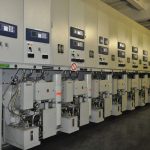
Power Management System
The Power Management System (PMS) objective is to enhance electrical power system safety and reliability. The SYSTEM uses computers and networking technology for enhancing plant electrical system safety, reliability, operability and maintainability.

Control Centers
Our SCADA systems are designed for control rooms within energy production, transmission and distribution and energy intensive manufacturing. We pack in a huge range of features and functions, and combine multiple tasks, areas and processes into a single system. The result is a cost-effective
Utility Communication
A reliable and secure data communication system is the backbone of any modern SCADA system. With extensive experience and knowledge, our utility communication products are a key competence of EMaC inclusive of components and support, providing practical solutions for critical infrastructure.
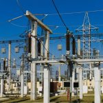
Substation Automation
Our substation automation products provides various protocols via RTU and reliable communication solutions including redundancy with a complete substation RTU controller. Our solutions include all features, for example, RTU functionality, Profibus, ProfiNET slave, Programmable logic controller functionality with reliable tasks.

Distribution Automation
Distribution automation products reach deep into the network to give you the detailed local intelligence that is crucial if you are to deliver a consistent and reliable supply and meet the expectations of electricity consumers. You can control the network and assets even beyond the transformer, at small switching stations
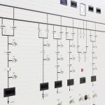
Mimic Mozaic Panels
The most affordable and durable solution for the representation & control of processes. You can efficiently and immediately monitor the status of connected system thanks to the framework of signal lights or sound and you can manage the operations by switches and selectors. We design the SCADA – Control System integrated, assemble & commission including their associated control circuits.